![]()
![]()
![]()
![]()
![]()
![]()
![]()
![]()
![]()
![]()
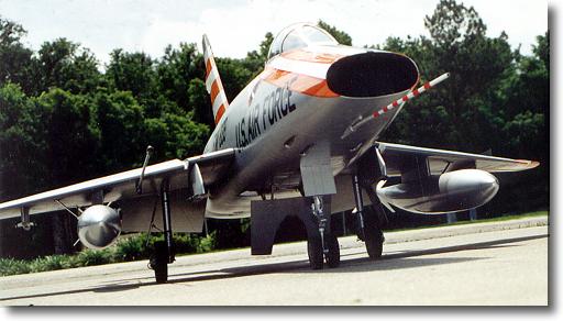
Specifications
LENGTH: 83.5"
WING SPAN: 69"
WING AREA: 1200 + sq. in.
WEIGHT: 29-31 lbs
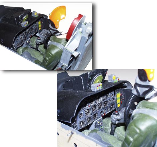
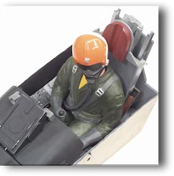
Kit Addendums | F-100 Scale Detail Parts by Dan Gill - NEW | Major Kit Components | Structure Highlights | Kit Pricing | F-100 in a Jet Case | Color Schemes | Super Scale Features| F-100 Landing Gear | Recent flights & video | Wing Fences | Refueling Probe & Pitot Tube | Cockpit | Gearing up your F-100 | Recent Updates | F-100 Sport Flying | Flying the REAL F-100F - NEW | Customers with their F-100's
![]() The model is sized to operate with a JetCat
P-120 or 160, AMT Pegasus, or RAM 1000 engine and weigh about 27 to 29 pounds.
Wing area is over 1,200 square inches.
The model is sized to operate with a JetCat
P-120 or 160, AMT Pegasus, or RAM 1000 engine and weigh about 27 to 29 pounds.
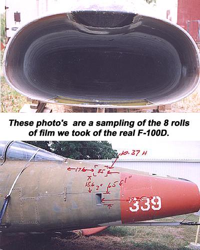
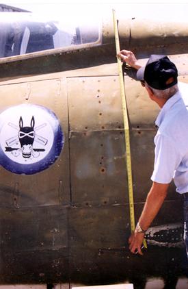
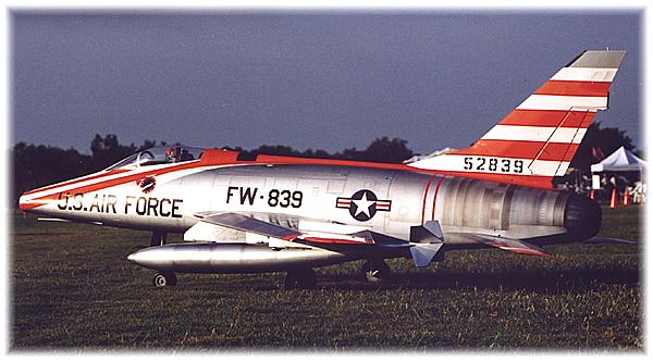
Wing area is over 1,200 square inches.![]() We reverse engineered a real bone yard F-100D to produce
an exact scale outline model - something that any scale jet enthusiast would be
proud to own.
We reverse engineered a real bone yard F-100D to produce
an exact scale outline model - something that any scale jet enthusiast would be
proud to own. ![]() The
F-100D is very easy to assemble and service and despite its size, it completely
disassembles to fit into the BVM JET-CASE, making it very easy to transport.
The
F-100D is very easy to assemble and service and despite its size, it completely
disassembles to fit into the BVM JET-CASE, making it very easy to transport.


See how the first flights went on the F-100.
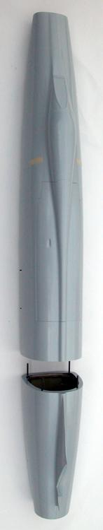
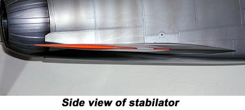
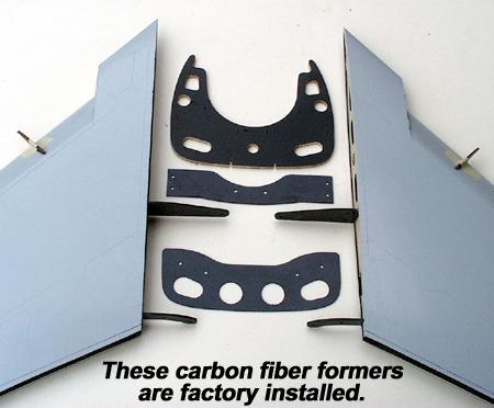
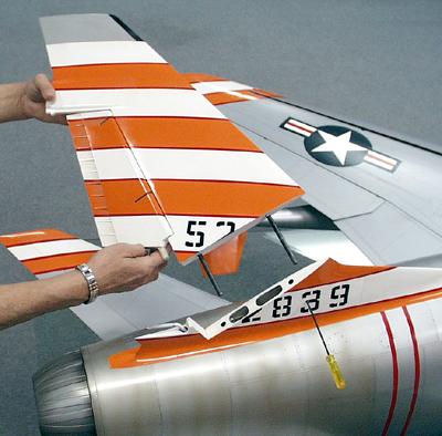
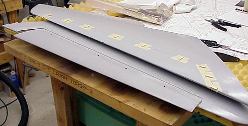
All components are composite except the
flaps. Flaps are built at the factory with hinges installed. Leading edge slat
tracks are factory installed for easy finishing. Stabs are checked for perfect
alignment on a surface plate and shipped bolted together as shown
above.
| F-100 Super Sabre Super Scale Feature "Thin Flying Surfaces" |
  |
 "Thin is in" on a real jet fighter |
|
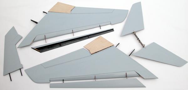
F-100D Structure highlights |
|
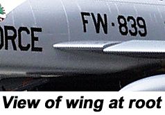
 The removable wing panels are all composite molded with every panel line faithfully reproduced. Two full depth and very strong carbon fiber spars carry the landing gear and flight loads (similar to the BVM F-4) and bolt to the carbon fiber bulkheads that are factory installed with accurate fixtures that guarantee perfect alignment. Putting the wing on the model at the field is a 10 minute affair. Access to the wing bolts is through the main wheel well openings. |
|
 |
|
Each leading edge slat rail has been custom fitted at the factory into the precision machined tracks that are built into the wings. The L.E. slats are molded of carbon fiber and have the "D" tube spar factory installed. The modeler does a very little bit of hand fitting, glues the slat to the rails and installs the operating servos. Leading edge slats have never been this easy and accurate. |
|
 The fin removes by loosening (2) set screws. With the wings and fin removed, the BVM F-100 transports and stores very conveniently even though it is a rather large model. |
|
 BVM makes a special "Jet Cradle" for the F-100 and our other kits to assist you in building the model and attaching the wings at the field. Jet Cradles can also serve to hold the model during transport. All of the components of the BVM F-100 have been extensively flight tested. Where we found need for improvement - we did so, before we released the kits. At BVM, our factory team pilots and reps fly alot so we can stay ahead on the learning curve. If we find a way to make your F-100 better, you can be sure that you will be informed. |
|
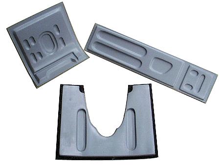
| Match molded Landing Gear Doors and Speed Brake | |
 |
|
| F-100 in a Jet Case |
 |
![]()
F-100
Airframe Directive (A.D.)
And other helpful notes
Large Fuel Cell Transfer
Tubes
Replace Brass with Stainless Steel
(4/20/06)
![]()
![]() There has been one case where the brass
tube that transfers fuel through a hole in the fuel cell baffle experienced
a razor saw-like cut. The engine flamed out because the remaining fuel below
the tube was unusable.
There has been one case where the brass
tube that transfers fuel through a hole in the fuel cell baffle experienced
a razor saw-like cut. The engine flamed out because the remaining fuel below
the tube was unusable.
![]()
![]() The most likely cause of the brass tubing
failure was many miles of trailer transport of the model with the fuel cells
empty.
The most likely cause of the brass tubing
failure was many miles of trailer transport of the model with the fuel cells
empty.
The Fix
![]()
![]() BVM
now supplies Stainless Steel tubes with the large baffled fuel cells i.e., KingCat,
F-100, F-4, Rafale, F-86 (80"). Retrofit parts are available. Ask for part
#PSTU003 (quantity 2) price $5.00 for the pair mailed within the USA.
BVM
now supplies Stainless Steel tubes with the large baffled fuel cells i.e., KingCat,
F-100, F-4, Rafale, F-86 (80"). Retrofit parts are available. Ask for part
#PSTU003 (quantity 2) price $5.00 for the pair mailed within the USA.
![]()
![]() To
be honest, we don't know how many travel miles the brass tubes will withstand.
It could vary quite a bit. BVM is converting our factory demo models as time
allows. Our prototype F-100D is 6 years old, has at least 300 flights and more
trailer miles than we can count. We inspected the brass tubes and found minimum
wear. We changed them to the Stainless Steel variety anyway.
To
be honest, we don't know how many travel miles the brass tubes will withstand.
It could vary quite a bit. BVM is converting our factory demo models as time
allows. Our prototype F-100D is 6 years old, has at least 300 flights and more
trailer miles than we can count. We inspected the brass tubes and found minimum
wear. We changed them to the Stainless Steel variety anyway.
Wing Pylon Mounting
F-100D & F
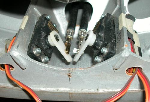
Stab Servo Arms
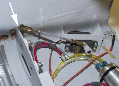
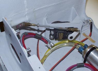
![]() The details and instructions on the top
view of the fuse plans show and emphasis that the stab pushrod clevises are
connected to the 2nd hole from the center of the JR 215 heavy duty arms.
THIS IS CORRECT.
The details and instructions on the top
view of the fuse plans show and emphasis that the stab pushrod clevises are
connected to the 2nd hole from the center of the JR 215 heavy duty arms.
THIS IS CORRECT.![]() The photo on page 54 of the "D" model and page 63 of the "F" model
should be replaced with this image.
The photo on page 54 of the "D" model and page 63 of the "F" model
should be replaced with this image.
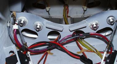
Trailer Transporting
the "Heavy
Jets"
![]() It is convenient to transport the F-100
and F-4 gear down and strapped to shelves in the trailer. However, we are
seeing some wear and tear on the wing mounting formers in the fuselage. The
#10-32 bolts are working loose and even stripping the threads on the carbon
fiber threaded discs. Of course, occasional stiff landings further aggrivate
this problem.
It is convenient to transport the F-100
and F-4 gear down and strapped to shelves in the trailer. However, we are
seeing some wear and tear on the wing mounting formers in the fuselage. The
#10-32 bolts are working loose and even stripping the threads on the carbon
fiber threaded discs. Of course, occasional stiff landings further aggrivate
this problem. ![]() Supporting the model on foam rubber on the trailer shelf should
greatly alleviate the problem.
Supporting the model on foam rubber on the trailer shelf should
greatly alleviate the problem. ![]() To fix a stripped out receptacle we made some aluminum
threaded inserts. See photo's for how to attach.
To fix a stripped out receptacle we made some aluminum
threaded inserts. See photo's for how to attach.
To add the threaded
aluminum inserts (BVM #2880) to the rear wing mounting formers, first scuff
with #80 grit, tack with slow CA, then surround with Aeropoxy.
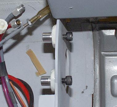
Use a 90° Dremel
tool and a Perma-Grit RF-5C to open holes in the forward wing mount former to
accept the aluminum insert shaft. Accomplish one at a time, checking alignment
with wing attached.
You should also
periodically check the 4-40 bolts that attach the main gear to the carbon fiber
wing spars.
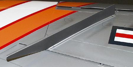
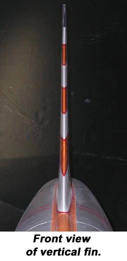
F-100 Rudder Trim
![]() It is hard to observe at a glance
because of the scale bulge in the fin at the top of the rudder and because the
rudder is thicker than the fuse fairing at the bottom. Take a close look before
take-off.
It is hard to observe at a glance
because of the scale bulge in the fin at the top of the rudder and because the
rudder is thicker than the fuse fairing at the bottom. Take a close look before
take-off.
F-100 Tailpipe Cooling Shroud
![]() A few of the very early kits may need
to have this part updated. The correct exit diameter at the rear of the outer
pipe is 3-3/4". If yours is less, return it for a no charge upgrade. The
upgrade deletes the need to wrap the outside of the pipe with the heat blanket.
The new system runs cooler.
A few of the very early kits may need
to have this part updated. The correct exit diameter at the rear of the outer
pipe is 3-3/4". If yours is less, return it for a no charge upgrade. The
upgrade deletes the need to wrap the outside of the pipe with the heat blanket.
The new system runs cooler.
F-100 Flap Geometry Improved
![]() A second look at the flap linkage
produced better results. It uses all of the same parts but realizes a better
advantage in both the up and full down position.
A second look at the flap linkage
produced better results. It uses all of the same parts but realizes a better
advantage in both the up and full down position.![]() As with any control surface linkage system, be
sure that the surface will travel freely beyond the prescribed limits so that
the servo is not under heavy load while commanding the desired deflection. For
the F-100 flaps, this means that the inboard ends do not bind on the fuselage
sides. Use a volt/amp meter to check for excess servo power drain.
As with any control surface linkage system, be
sure that the surface will travel freely beyond the prescribed limits so that
the servo is not under heavy load while commanding the desired deflection. For
the F-100 flaps, this means that the inboard ends do not bind on the fuselage
sides. Use a volt/amp meter to check for excess servo power drain.![]() The system shown has been
thoroughly flight tested in our F-100F.
The system shown has been
thoroughly flight tested in our F-100F.
Note servo arm angle with flaps
full up. Clevis is in 1st hole of JR heavy duty servo arm and the 2nd hole on
the metal flap horn. Do not neglect the wood shim, flaps up stop
(arrow).
Note angle of the servo arm in the
flaps down position.
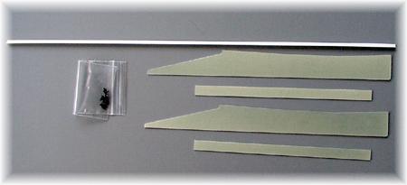
Installing the Slats
![]() Steven Ellzey is a super precise
craftsman as well as being an Aerospace engineer, so I am sure F-100 builders
can benefit from his slat technique.
Steven Ellzey is a super precise
craftsman as well as being an Aerospace engineer, so I am sure F-100 builders
can benefit from his slat technique.
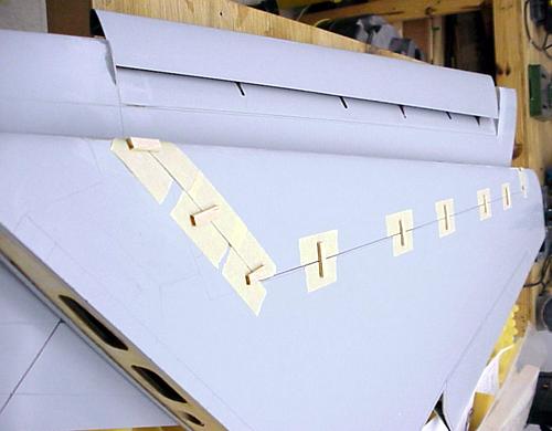
Steven says:![]() I finished up getting the
slats on the Hun, and they turned out working very smoothly (if you pick the
wing up leading edge down they will fall on the floor). I thought I would pass
on what I did, should it be of any help.
I finished up getting the
slats on the Hun, and they turned out working very smoothly (if you pick the
wing up leading edge down they will fall on the floor). I thought I would pass
on what I did, should it be of any help. ![]() For fitting and gluing, a
layer of masking tape was applied to each side of the rails where they go into
the wing. This forced the rail to the center of the slot. The opening into the
spar on the slat was made a bit over sized, and the top of the rail, where it
meets the slat, was cut back a bit extra (1/64"). This was done so that when
the slat was held in place it would not touch, and possibly bend, the rails.
The slat was held in place by several pieces of balsa, CAed to masking tape
(see attached photos). This made sure that the OML (outer most layer) of the
slat matched the OML of the wing on the top. I also applied a thin layer of CA
to the edges of the rails where they go into the wing and polished it with 600
grit. I did this after the fact on one side and it seemed to help a bit when
the slat was loaded vertically. On the other side, I CAed and polished before I
glued them in (much easier). Other than the CA and polishing on the first side,
no work was done on the rails after being glued in.
For fitting and gluing, a
layer of masking tape was applied to each side of the rails where they go into
the wing. This forced the rail to the center of the slot. The opening into the
spar on the slat was made a bit over sized, and the top of the rail, where it
meets the slat, was cut back a bit extra (1/64"). This was done so that when
the slat was held in place it would not touch, and possibly bend, the rails.
The slat was held in place by several pieces of balsa, CAed to masking tape
(see attached photos). This made sure that the OML (outer most layer) of the
slat matched the OML of the wing on the top. I also applied a thin layer of CA
to the edges of the rails where they go into the wing and polished it with 600
grit. I did this after the fact on one side and it seemed to help a bit when
the slat was loaded vertically. On the other side, I CAed and polished before I
glued them in (much easier). Other than the CA and polishing on the first side,
no work was done on the rails after being glued in.
 |
 |
![]() The only problem I see so far is that the
slats are a bit thinner than the wing. Since I made the upper surface match as
is, I will putty the lower surface to match the lower OML of the wing, which
should be fairly easy to do. So far this looks like a very slick piece of
machinery.
The only problem I see so far is that the
slats are a bit thinner than the wing. Since I made the upper surface match as
is, I will putty the lower surface to match the lower OML of the wing, which
should be fairly easy to do. So far this looks like a very slick piece of
machinery.![]() Steven Ellzey
Steven Ellzey
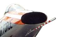
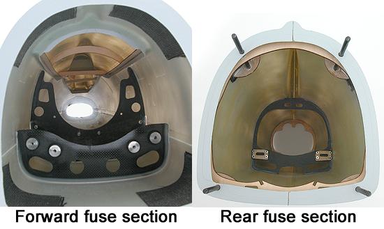
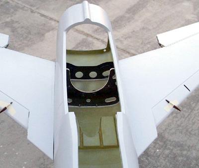
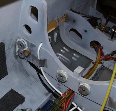
Inlet / Fuse Joint
![]() The forward inlet/fuse joint can be
strengthened to reduce distortion during high power static and low air speed
run-ups and to prevent damage while handling the model. This can be
accomplished during construction or on a completed model.
The forward inlet/fuse joint can be
strengthened to reduce distortion during high power static and low air speed
run-ups and to prevent damage while handling the model. This can be
accomplished during construction or on a completed model.![]() Once the forward inlet
duct section has been glued in according to the instructions, position the fuse
nose down onto a flat surface (cover with wax paper) and pour a mixture of
resin and micro-balloons through the openings of F-1.
Once the forward inlet
duct section has been glued in according to the instructions, position the fuse
nose down onto a flat surface (cover with wax paper) and pour a mixture of
resin and micro-balloons through the openings of F-1.![]() Use one and one half
ounces of Pacer Finishing Resin mixed with micro-balloons to form a thickened,
but still pourable slurry.
Use one and one half
ounces of Pacer Finishing Resin mixed with micro-balloons to form a thickened,
but still pourable slurry.![]() Allow to cure with fuse in vertical position.
Allow to cure with fuse in vertical position.
F-100 Stabilator Control Horns
some
were tapped 4-40 vs 5-40
![]() Our vendor for this part misread the
print and we did not catch the mistake prior to shipping some of these
units.
Our vendor for this part misread the
print and we did not catch the mistake prior to shipping some of these
units.![]() Check that
the part in your kit is properly setup for the #5-40 bolts that mount the
pushrods. If it is not, return it for a replacement. If you have a #38 drill
and 5-40 tap, you can correct the part in your shop.
Check that
the part in your kit is properly setup for the #5-40 bolts that mount the
pushrods. If it is not, return it for a replacement. If you have a #38 drill
and 5-40 tap, you can correct the part in your shop.![]() Sorry for the
inconvenience.
Sorry for the
inconvenience.
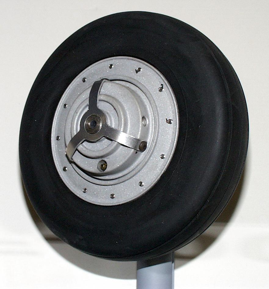
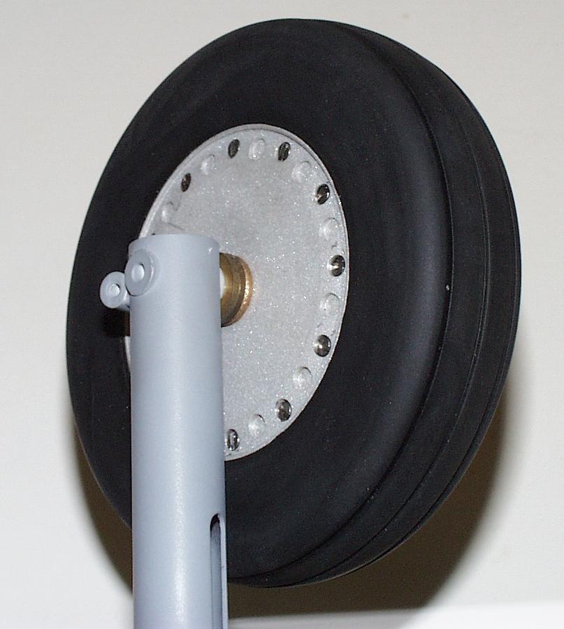
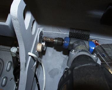
F-100 Wheel Brakes Retention
![]() Note that the wheel brake hub is
retained to the axle with (2) "dog end" set screws that seat into a hole
through the wheel axle and are locked in place with secondary set
screws.
Note that the wheel brake hub is
retained to the axle with (2) "dog end" set screws that seat into a hole
through the wheel axle and are locked in place with secondary set
screws.![]() After
several flights you can check the security of these screws with a 5/64" hex
wrench.
After
several flights you can check the security of these screws with a 5/64" hex
wrench.![]() We have
observed that after about 80 flights on our "D" model, the "dog end" set screw
is slightly bent but still functional.
We have
observed that after about 80 flights on our "D" model, the "dog end" set screw
is slightly bent but still functional.![]() Spare set screw sets are available - a nice addition to
your spare parts kit. Add it to your next order and save on the
postage.
Spare set screw sets are available - a nice addition to
your spare parts kit. Add it to your next order and save on the
postage.![]() Package #5828 contains:
Package #5828 contains:![]() (4) dog end 8-32 x 3/8"
(4) dog end 8-32 x 3/8"![]() (4) set screw 8-32 x
1/4"
(4) set screw 8-32 x
1/4"![]() Price:
$4.00
Price:
$4.00
F-100 Slat Servos
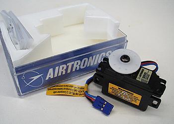
![]() JR has
discontinued the 3321 servo that we call for in the instructions for use on the
slats.
JR has
discontinued the 3321 servo that we call for in the instructions for use on the
slats.![]() The
replacement digital variety #3301 are temporarily out of stock. The Airtronics
94141 (metal gear) makes an excellent substitute. Two standard and two reverse
units are required. These servos allow manual operation of the slats. We always
like to see the slats extended for static display. See your Airtronics dealer.
F.T.E. has these units in stock - call 561-795-6600.
The
replacement digital variety #3301 are temporarily out of stock. The Airtronics
94141 (metal gear) makes an excellent substitute. Two standard and two reverse
units are required. These servos allow manual operation of the slats. We always
like to see the slats extended for static display. See your Airtronics dealer.
F.T.E. has these units in stock - call 561-795-6600.![]() BV's new F-100F utilizes
the 94141's on the slats.
BV's new F-100F utilizes
the 94141's on the slats.
F-100 Speed Brake / Wheel Brakes
mix on the JR
10X
![]() We mixed the speed brake to the wheel brakes and assigned the
control to the Aux 3 channel.
We mixed the speed brake to the wheel brakes and assigned the
control to the Aux 3 channel.![]() The first 90% of side lever travel provides proportional braking for
taxi control. The last 10% activates the speed brake air valve servo control
servo.
The first 90% of side lever travel provides proportional braking for
taxi control. The last 10% activates the speed brake air valve servo control
servo. ![]() I prefer
to fly the final approach with the speed brake deployed so that the glide slope
and touchdown point is very precisely controlled with power. Touching down with
the brakes "on" will yield a short roll out of about 200ft. If this is not
desired, move the Aux 3 lever just a bit prior to touchdown to release the
"full on" brakes and hold the nose high for a full flare landing.
I prefer
to fly the final approach with the speed brake deployed so that the glide slope
and touchdown point is very precisely controlled with power. Touching down with
the brakes "on" will yield a short roll out of about 200ft. If this is not
desired, move the Aux 3 lever just a bit prior to touchdown to release the
"full on" brakes and hold the nose high for a full flare landing.![]() For Futaba 9ZAP users
there is a device called the electronic switch that will help free up a
channel. BVM rep Paul Bageman has some experience with this item.
For Futaba 9ZAP users
there is a device called the electronic switch that will help free up a
channel. BVM rep Paul Bageman has some experience with this item.
Landing Heavy
and Fail Safe setup
![]() I had one occasion at Jets over Deland (Jan
'01) where the radio was indicating fail safe conditions shortly after
take-off.
I had one occasion at Jets over Deland (Jan
'01) where the radio was indicating fail safe conditions shortly after
take-off.![]() I always
set the fail safe as follows:
I always
set the fail safe as follows:![]() Engine to idle, gear down, and a slight amount of up
stab.
Engine to idle, gear down, and a slight amount of up
stab.![]() The
"Hun" was on the downwind leg when I saw the gear extend, so I immediately
entered the landing pattern, dirtied up and set the power appropriately for a
heavy landing.
The
"Hun" was on the downwind leg when I saw the gear extend, so I immediately
entered the landing pattern, dirtied up and set the power appropriately for a
heavy landing.![]() With about 90% of the 4.8 Liters of fuel remaining the slatted wing
handled the extra 5-6 pounds of fuel (above a normal landing) very well - just
keep the power on.
With about 90% of the 4.8 Liters of fuel remaining the slatted wing
handled the extra 5-6 pounds of fuel (above a normal landing) very well - just
keep the power on.![]() This experience confirms that we can add a few extra pounds worth of
missiles and bombs and enjoy the ultimate airborne appearance. Plenty of
reliable power is all that is needed.
This experience confirms that we can add a few extra pounds worth of
missiles and bombs and enjoy the ultimate airborne appearance. Plenty of
reliable power is all that is needed.
Stab Servos - shim
![]() To keep the servo cases from interfering with
the bottom fuse skin, it is necessary to add 1/8" ply shims to the inboard
faces of the stab servo mounts. BV's model has the bottom of the servo cases
protruding very slightly to keep a close check on servo temps after flight. So
far no problems, holes in the bottom of the fuse are not
necessary.
To keep the servo cases from interfering with
the bottom fuse skin, it is necessary to add 1/8" ply shims to the inboard
faces of the stab servo mounts. BV's model has the bottom of the servo cases
protruding very slightly to keep a close check on servo temps after flight. So
far no problems, holes in the bottom of the fuse are not
necessary.
Stab Control Yoke
![]() A very few parts may have been shipped out
with 4-40 threaded holes vs. the correct 5-40 threads. Contact BVM if you
received a 4-40 set.
A very few parts may have been shipped out
with 4-40 threaded holes vs. the correct 5-40 threads. Contact BVM if you
received a 4-40 set.
3-View Drawings
![]() We used the drawings from the War Paint Series
#4 booklet. 11" x 17" copies of the top, side and front view of the F-100D are
available from BVM.
We used the drawings from the War Paint Series
#4 booklet. 11" x 17" copies of the top, side and front view of the F-100D are
available from BVM.