 

July
'01
The following information and photo's will help
clarify a few fine points of gearing up the F-100D.
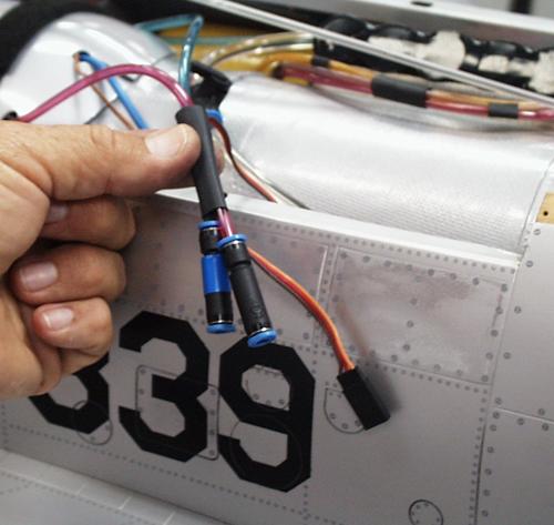
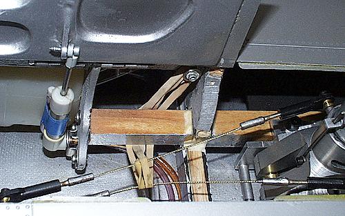
Stabilator
servo wiring
Locate the "Y" harness close to the
receiver and be able to access the two connections to the 36" leads. Before
each flying session, disconnect one at a time to ensure that both 8411 servos
are functioning. Do not use servos with less power than 150oz/inches of
torque.
Speed Brake
control
The prototype has the speed brake
activated by the same channel (Aux 3, JR) as the wheel brakes. The last few
degrees of travel of the slide switch on the transmitter commands the speed
brake to open.
Approaches and landings on short runways are accomplished
with the speed brake deployed and the brakes full "on". Landing roll out will
be about 200ft. Tire wear is not excessive.
Fuel
System
Incorporate a BVM Ultimate Air Trap
(U.A.T.) into the fuel system. Place it in the fuse on the left side of the
inlet duct. Rig the 16oz. header tank as a 2 line system and fill through the
3rd line on the U.A.T.
Retract
System
Add a 2nd air tank (BVM #4204) to the
retract system. "T" it into the other tank to increase the volume of air
available to operate the landing gear.
Use a BVM modified Robart 4-way
valve marked "Retracts" or "Gear" to control the system.
Retracts and
Door Cycler
Use the programmable unit available
from Mini Hobby Atl. or BVM. The time between the gear "up" command and the
door closing should be 6-7 seconds to allow for air load delays on the landing
gear. The door command on the down cycle can be 4 to 5 seconds.
It is a
good procedure to check the gear operation before each flight. Observe that
there are no severe air leaks in the up or down position. A fill pump with a
guage will assist here.
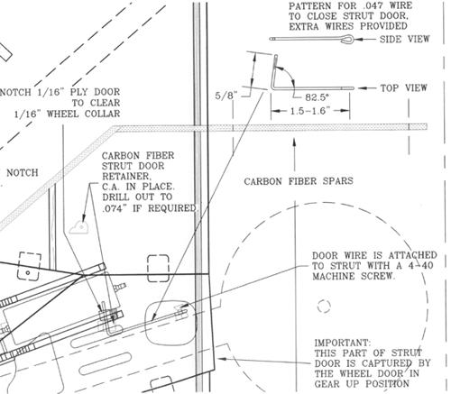
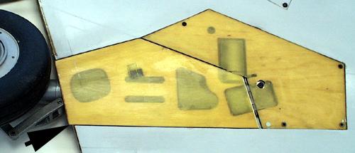
Main wheel well
door stops
The edges of the main wheel well doors
are thicker than the fuse skin. Therefore, the poly ply strips on the fuse
opening that serve as seats for the doors, must be offset from the inside fuse
skin accordingly. Use strips of 1/64" ply (cross grain) to
accomplish.
Forward inlet
glue joint
Improper handling of the forward end
of the fuse can cause the glue joint between the front of the fuse and the
inlet to fracture. Subsequent full power run-ups may cause the inlet to deform.
Check this glue joint often and look down the inlet occassionally during a
ground run up. The pressure drop in the inlet during forward flight is
considerably less.
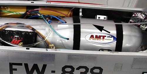 |
JR 1800 mah
5-cell pack powers the radio system - charge after 2 flights with Graupner MC
Ultra Duo plus. Antenna is on center and suspended 1" or more off the top of
the bypass, make notch in aft flange of hatch as
necessary.
|
 |
Start air,
propane and data terminal connections for AMT are accessed through main
hatch.
|
Bevel this edge if
necessary to clear tire
 |
|
 |
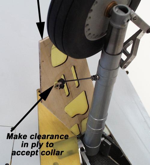
| Main strut
door attachment is by .047" wire. Loop end attaches to strut. Bend out board
end and attach to CF part with small wheel collar. Fine tuning of outboard end
angle determines door closing. Drilling hole in CF part oversize may assist.
Bottom edge of strut door will just about touch the tire during up cycle.
Relieve door if necessary. The brake line is taped to strut and routed through
the axle. Secure all air lines to not interfere with retract
action. |
Lower aft
end of door must extend into fuse, thus, the wheel well door traps it in place
for flight. |
|
 |
1/32" nose
gear steering cables use ball/socket linkage on both ends. They are kept out of
way of retracting strut with (2) light rubber
bands.
|
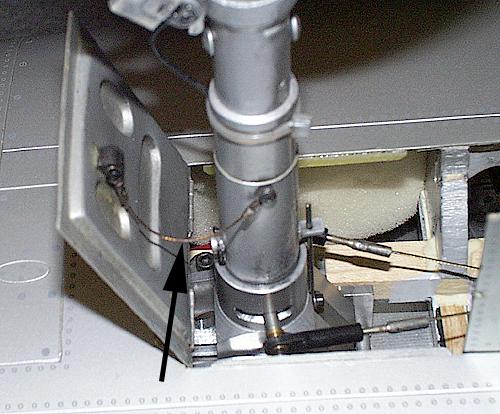 |
The nose
gear fwd door is attached to the strut with fishing line cable and 2 crimps.
One end is secured to the CF strut door attachment and the other is secured to
the strut with button head panel screws.
|
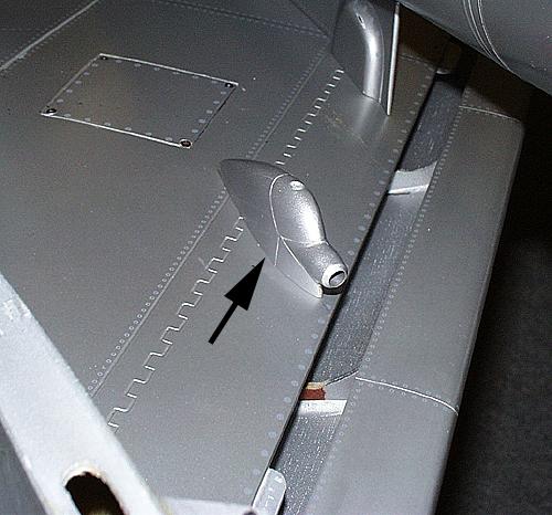 |
| Molded
refueling probe mount is attached to the bottom of the right wing. |
F-100 customers who need any of these parts to
complete the gearing-up process, please let us know.

Contact Us
All graphics, photos, and text
Copyright 2016 BVM, Inc.
Use of graphics or photos without written permission from
BVM is
strictly prohibited. |