 

Assembly and Operational Manuals
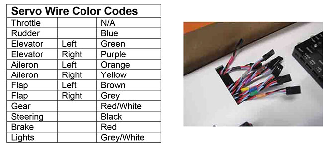
BVM Light
Controller Wiring Diagrams
Version 1
Version 2
| Bandit
evo EVF Version
Click here to download (pdf file) (3,888
KB)
Bandit evo
Turbine Version
Click here to download (pdf file) (6,831
KB)
Central
Control Unit
Click here to download (pdf file) (779
KB)
Cougar
Click here to download (pdf file) (4,641
KB)
F-1
Mirage Throws
Click here to download (pdf file) (62
KB)
F-100
Click here to download (pdf file) (2,174
KB)
F-15
Click here to download (pdf file) (909
KB)
Throws
Click here to download (pdf file)
F-16 1:5
scale
Click here to download (pdf file) (7,162
KB)
Throws
Click
here to download (pdf file) (543
KB)
F-16 1:6
scale
Click here to download (pdf file) (9,254
KB)
Throws
Click
here to download (pdf file) (67
KB)
F-18C 5.5
scale
Click here to download (pdf file) (4,312
KB)
F-18F
1:7.5 scale
Click here to download (pdf file) (1,758
KB)
KingCat V2
Click here to download (pdf file)
Renegade
Click here to download (pdf file)
(1,519 KB)
Sabre 5.8
scale
Click here to download (pdf file) (3,582
KB)
Sabre 1:7
scale EVF Version
Click here to download (pdf file) (2,638
KB)
Sabre 1:7
scale Turbine Version
Click here to download (pdf file)
L-39
Click here to download (pdf file) (3,133
KB)
Ultra
Bandit evo
Click here to download (pdf file) (2,227
KB)
Viper
Click here to download (pdf file) (4,678
KB)
Viper (2024
Version)
Click here to download (pdf file)
Yak130
1:4.85 scale
Click here to download (pdf file) (5,920
KB) |
Tomahawk F-86
Click here to download (pdf file) (11
KB)
Tomahawk Hawk
Click here to download (pdf file) (1.70
MB)
CG
& Throws
|
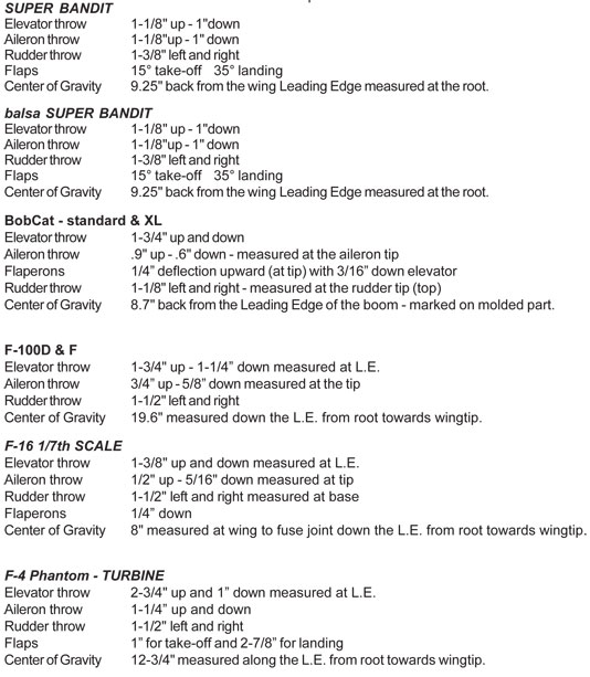
F-100 GFG
Center of Gravity
The CG mark on the side of the fuse should be at 15.3 inches. This is a
great starting point. Balance the model fully assembled, with all batteries
in and gear down.
Elevator Neutral
NOTE: The elevator neutral is .25” below the panel line at the fuse side.
Control Surface Deflections and Expo Settings
NOTE: The BVM Demo plane is set up using the following Expo percentages.
Positive values are used on Spektrum and JR radios, Futaba uses negative.
|
Control |
High Rate
Travels |
|
Expo |
D/R M |
D/R L |
|
Stab (measured
at the fuse side LE.) |
Up 1.75” |
DN 1.25” |
20 |
80%/15 |
50%/10 |
|
Aileron
(measured at the flap aileron joint) |
3/4”UP |
5/8”DN |
20 |
80%/15 |
50%/10 |
|
Flaps (measured
at the flap aileron joint) |
Take Off 1”
|
Landing 2.5 ” |
|
|
|
|
Rudder
(measured at the Bot.) |
L&R 1.5” |
|
20 |
80%/15 |
50%/10 |
|
|
F-15
Center Of Gravity
The Center of Gravity comes pre-marked from the factory. Verify that it is
marked at 2” forward of the front spar.
Control Deflections
|
Surface |
Direction |
Measurement Location |
Low |
Medium |
High |
|
Rudder |
Left/Right |
Base of Rudder |
.75” |
.90” |
1.2” |
|
Elevator |
Up/Down |
Use Template provided |
|
|
|
|
Aileron |
Up/Down |
Ail/Flap Junction |
.75” |
.90 |
1.1” |
|
Expo: Typically 15%-25% is used on all surfaces. This is pilot’s
discretion |
| |
|
|
|
|
|
|
Flap Settings |
Measurement |
Measurement Location |
|
|
|
|
Takeoff |
1.0” |
Flap/Aileron Junction |
|
|
|
|
Landing |
2.25” |
|
|
|
|
|
eBandit EVO
Center of Gravity
Measure 8.7" to 9.0" AFT
the leading at Wing Fuse Joint.
|
|
Bandit EVO
Center of Gravity
Measure 8.7" to 9.0" AFT the
leading at Wing Fuse Joint.
|
|
F-16
1:5 Scale
Center of Gravity
Measure aft of the
front/rear fuselage joint 8.5”. Drill a 1/16” hole in the fuselage skin 1/4”
inboard from the wing root.
Install a #2 button head
screw on each side. The root of the fuselage also has the GC location marked
with a pen. This location is very forgiving; there is no need to move it
forward. The second BVM demo plane is set slightly aft per pilot’s choice.
Balance the model fully
assembled, empty fuel tanks, gear down, and a full UAT. With the correct CG,
the model should balance level.
Control Deflections
Note: The BVM Demo
plane is set up using the following Expo percentages. Positive values are
used on Spektrum and JR radios, Futaba uses negative.
|
Control |
High Rate |
Expo |
|
Stabilator
(measured at the L.E.) |
Up 1.4”
Down 1.6” |
Up 17% Down 21% |
|
Aileron
(measured at the Root) |
+/- ”1.8” |
10% / 10% |
|
Flaps- (Take-Off &
Landing)
(measured at the
Root) |
.4” |
|
|
Rudder (measured
at the Bot.) |
+/- 1.25” |
10% / 10% |
Note: This model’s
single flap setting was based on the full scale F-16. Anytime the gear was
lowered or raised, the flaps went to a preset position.
|
|
F-16
1:6 Scale
Center of Gravity
Measure aft of the
front/rear fuselage break 10.5”. Drill a 1/16” hole in the fuselage skin
1/4” inboard from the wing root and install a #2 button head screw on each
side. The root of the fuselage also has the GC location marked with a pen.
This location is very forgiving; there is no need to move it forward. The
second BVM demo plane is set slightly aft per pilot’s choice.
Balance the model fully
assembled, empty fuel tanks, gear down, and a full UAT. With the correct CG,
the model should balance level.
Control Deflections
|
Control |
High Rate |
Expo |
Medium Rate |
Expo |
Low Rate |
Expo |
|
Stabilator
(measured at the L.E.) |
Up 1-5/8” Down
1-1/2” |
Up 17% Down 21% |
Up 1-1/4”
Down 1-1/4” |
Up 18% Down 22% |
Up 1” Down 1” |
Up 8% Down 12% |
|
Aileron
(measured at the Root) |
+/- 1-3/8” |
10% / 10% |
+/- 1-1/16” |
10% / 10% |
+/- 7/8” |
10% / 10% |
|
Rudder (measured
at the Bot.) |
+/- 1-1/8” |
10% / 10% |
+/- 3/4” |
8% / 8% |
+/- 1/2” |
0% / 0% |
Note: The BVM Demo
plane is setup using the following Expo percentages. Positive values are
used on Spektrum and JR radios, Futaba uses negative.
|
|
F-18C 1:5.5 Scale
Control Deflections
Note: The BVM Demo
plane is set up using the following Expo percentages. Positive values are
used on Spektrum and JR radios, Futaba uses negative.
|
Control |
High Rate |
Expo |
|
Stabilator
(measured at the L.E.) |
Up 2.25”
Down 1.6” |
Up 20% Down 20% |
|
Aileron
(measured at the Flap Aileron joint) |
+/- ”1.25” |
20% / 20% |
|
Flaps- (Take-Off &
Landing)
(measured at the
Flap Aileron joint) |
Take Off
.75” |
Landing
2.25” |
|
Rudder (measured
at the Bot.) |
+/- 1.5” |
20% / 20% |
|
F-18F 1:7.75 Scale
Center of Gravity
The
Center of Gravity comes pre-marked from the factory. Verify that it is
marked at 4.5” back from the corner as shown.
To help mark the Center
of Gravity position when the wing is in place, you can use two Buttonhead
screws on the bottom of fuse at the fuse wing joint. (BVM # 5625)
Control Deflections
|
Surface |
Direction |
Measurement Location |
Low |
Medium |
High |
|
Rudder |
Left/Right |
Top of Rudder |
¾” |
⅞” |
1-⅛” |
|
Elevator |
Up/Down |
Leading Edge of Stab |
1-⅛” |
1-½” |
1-⅞” |
|
Aileron |
Up/Down |
Ail/Flap Junction |
¾” |
1” |
1-¾” |
|
Expo: Typically
15%-25% is used on all surfaces. This is pilot’s discretion |
|
Flap Settings |
Measurement |
Measurement Location |
|
|
|
|
Takeoff |
⅞” |
Flap/Aileron Junction |
|
|
|
|
Landing |
2-½” |
|
|
|
|
Elevator Trim |
Measurement |
Measurement Location |
|
|
|
|
Flaps UP Gear UP |
3” |
Down from Vertical Fin Junction at the Stab Leading Edge |
|
|
|
|
Flaps Takeoff
Gear Down |
3-⅜” |
|
|
|
|
Flaps Landing
Gear Down |
3-⅝” |
|
|
|
|
*These measurements
are a good baseline. |
|
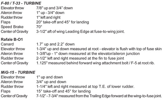
Cougar 1:5.8 Scale
Center Of Gravity
Measure aft
of the Leading Edge (LE) at the wing/fuse joint 9.25”. Drill a 1/16” hole in
the fuselage skin 1/4” inboard from the wing root and install a #2 button
head screw on each side. This location is very forgiving; there is no need
to move it forward.
Balance the model fully
assembled, empty fuel tanks, gear down, and a full UAT. With the correct CG,
the model should balance level.
Control Surface Deflections and Expo
Settings
|
Control |
High Rate |
Expo |
Medium Rate |
Expo |
Low Rate |
Expo |
|
Elevator (measured at the Root) |
Up 1”
Down 1” |
Up 7% Down 7% |
Up 15/16”
Down 15/16” |
Up 4% Down 4% |
Up 7/8”
Down 7/8” |
Up 2% Down 2% |
|
Aileron (measured at the Ail/Flap
Junction) |
Up 1-7/16”
Down 1-1/8” |
12% / 12% |
Up 1-1/4”
Down 1-1/16” |
5% / 5% |
Up 1-1/8”
Down 1” |
3% / 3% |
|
Rudder (measured at the Bottom of
the top rudder) |
+/- 1-1/8” |
10% / 10% |
|
|
|
|
|
Control |
Take-Off Position |
Landing Position |
|
|
|
|
|
Flaps |
1/2” |
7/8” |
measured at the Ail/Flap Junction |
|
Body Flaps |
1-7/8” |
3-3/4” |
See Photo Below |
|
Elevator Mix with flaps |
1/8” Up |
3/16” Up |
measured at the Root |
|
|
Mid Position |
Full Position |
|
|
|
|
|
Speed Brake |
1-1/2” |
3” |
Measured at the outside corner |
Note: The BVM Demo
plane is setup using the above Expo percentages. Positive values are used on
Spektrum and JR radios, Futaba uses negative.
|
|
L-39 1:5 Scale
Center Of Gravity
The factory puts an inked
C.G. mark on the fuselage wing fairing. It is better to transfer that
location to the bottom of the fuse fairing. Make a 1/16” hole 5.6” aft of
the wing L.E. at the root on the fuse. Install a small button head screw on
both sides of the fuse.
A helper is necessary to
balance the model with fuel only in the UAT and a half full 16oz. header
tank. Our demo model needed no ballast. Minor adjustments of the ECU battery
location will suffice.
Control Surface Deflections and Expo
Settings
|
Control |
High Rate |
Expo |
|
Elevator (Measured at the Root) |
Up 1.5”
Down 1.25” |
Up 30% Down 0% |
|
Aileron (Measured at the Ail/Flap
Junction) |
Up 1”
Down 0.9” |
25% / 25% |
|
Rudder (Measured at the bottom of
the top rudder) |
L/R 1.4” |
10% / 10% |
|
Control |
Take-Off Position |
Landing Position |
|
Flaps
(Measured at Fuse root) |
1.2” |
3.1” |
|
Speed Brake |
70º open |
|
Note: The BVM Demo
plane is setup using the above Expo percentages. Positive values are used on
Spektrum and JR radios, Futaba uses negative.
Note: This chart
reflects only medium rates for the ailerons, elevator, and rudder. Higher
rates and expo settings are at pilot’s discretion but not necessary for safe
aerobatic flight. |
|
F-86 1:7 Scale -
Electric Version
Center of Gravity
The Center of Gravity is located on the forward inboard screw
of the main gear flex plate.
NOTE:
Your final C.G. can be fined tuned by moving your BVM Flight packs forward
or aft.
Control Surface Deflections and Expo
Settings
|
Control |
High
Rate |
Expo |
Medium Rate |
Expo |
Low
Rate |
Expo |
|
Elevator
(measured at the Root) |
Up .75”
Down
.5” |
Up 20%
Down 20% |
Up .5”
Down .5” |
Up 15%
Down 15% |
|
Up 10%
Down 10% |
|
Aileron (measured at the Ail/Flap Junction) |
Up .80”
Down
.80” |
20% /
20% |
Up .60”
Down
.60” |
15% /
15% |
Up .50”
Down
.50” |
10% /
10% |
|
Rudder (measured at the Bottom of the top rudder) |
Left
1.0”
Right 1.0” |
20% /
20% |
Left
.75”
Right .75” |
15% /
15% |
Left .5”
Right .5” |
10% /
10% |
|
Control |
Take-Off Position |
Landing Position |
|
|
|
|
|
Flaps |
.70” |
1.8” |
measured at the Ail/Flap Junction |
|
Elevator Mix with flaps |
.20” Up |
.25” Up |
measured at the Root |
Note:
The BVM Demo plane is setup using the above Expo percentages. Positive
values are used on Spektrum and JR radios, Futaba uses negative.
|
|
Viper
Center of Gravity
NOTE: The Center of Gravity symbol on the
fuselage side may be incorrect on some early models.
Use a 1/16" drill bit located 9.5" aft of
the L.E. of the wing strake. Drill 1/16" holes in the bottom of both wings.
NOTE: Position of ECU and Receiver batteries
allow fine adjustments to obtain proper Center of Gravity.
CONTROL TRAVELS
|
Control |
High Rate |
Expo |
|
Elevator (Measured at
the Root) |
Up 1.0”
Down 0.75” |
Up 25% Down 25% |
|
Aileron (Measured
at the Tip) |
Up 0.6”
Down 0.6” |
30% / 30% |
|
Rudder (Measured at
the base) |
L/R 1.3” |
20% / 20% |
|
Control |
Take-Off Position |
Landing Position |
|
Flaps (Measured at
Fuse root) |
1” |
2.3” |
|
Crow (Ailerons)
(Measured at Tip)
In landing mode with
landing flaps |
Up 0.3" |
|
NOTE:
Crow Set-Up: Positioning the Ailerons (up) with landing Flaps down. This
adds stall protection during the approach.
|
|
YAK-130 1:4.85 Scale
Center of Gravity
The C/G is 6” aft of the
leading edge fairing on the fuselage as shown.
The C/G is also located by
the factory with ink on the side of the wing fairing.
Control Surface
Deflection and Expo Settings
NOTE: Use
the medium rate travels for the first flight with appropriate rate switches
in the mid position. Expo values vary with pilot preferences.
|
Control |
High Rate |
Expo |
Medium Rate |
Expo |
Low Rate |
Expo |
|
Stabilator
(measured at the T.E.) |
Up 1-5/16”
Down 1-1/16” |
Up 17% Down
21% |
Up 1-1/4”
Down 1-1/4” |
Up 18% Down
22% |
Up 1”
Down 1” |
Up 8% Down
12% |
|
Aileron
(measured at the Outboard Tip) |
+/-
3/4” |
10% / 10% |
+/-
5/8” |
10% / 10% |
+/-
1/2” |
10% / 10% |
|
Rudder
(measured at the Top) |
+/-
1.25” |
10% / 10% |
+/-
1” |
8% / 8% |
+/-
3/4” |
0% / 0% |
Note:
The BVM Demo plane is setup using the following Expo percentages. Positive
values are used on Spektrum and JR radios, Futaba uses negative.
Flaps Take
Off 3/4” Landing 2”
Note:
Measure from fuselage wing root fairings
Stabilator = Neutral at 2”
from fuse top.
A= Up To pitch nose up
B= Down To pitch nose down |
|
eBandit
Aileron Throw
Surface travel measured at the tip should be: DOWN - .6" UP - .7"
Rudder Throw
Surface travel measured at the tip should be: RIGHT - .8" LEFT - .8"
Elevator Throw
Surface travel measured at the tip should be: DOWN - .5" UP - .6"
Flap Throw
Surface travel measured at the root T.E. should be: TAKE OFF - 1-1/4"
LANDING - 2-3/4".
Center Of Gravity
Balance the eBandit with the gear down and the batteries
in place. The balance point is identified on the bottom of the fuselage by
locating the two 1/16" holes drilled by BVM. They should be 8-3/4" aft of
the L.E. at the wing-to-fuse junction. Install 2 small button head screws to
mark the C.G. position. C.G. position is controlled by battery location.
Mark the fuselage flanges accordingly after test flights.
Balance the wings by weighing them individually. Add weight to the light
wing as follows – example – right wing is 1 oz heavier than the left, add 1
oz of lead in the aileron servo pocket of the left wing. Glue the lead in
securely.
F-86 84"
Aileron Deflection - Measured at outboard tip
High Rate: up = .90" down = .60"
Medium Rate: up = .70" down = .45"
Flaps Deflection - Measured at inboard root T.E.
Take-off = 1.60"
Landing = 3.00"
Elevator Deflection- Measured at the root T.E., molded-in dot is neutral.
1.25" up (above dot)
1.0 "down (below dot)
Rudder Deflection - Measured at root T.E.
1.5" Left and Right
Center of Gravity- Measure with gear down and UAT full.
22.7" From root leading edge, 0.75" back. (Factory Drilled Hole)
|
 |
 |
 |
 |
 |
Contact Us
All graphics, photos, and text
Copyright 2022 BVM, Inc.
Use of graphics or photos without written permission from
BVM is
strictly prohibited. |